Cable-Driven Parallel Robot for Submerged Applications
This project serves as my final project for the MS in Robotics program at Northwestern University. The overall goal was to build and develop software for a system capable of reliable operation while submerged in water. I designed and built the system for 7 weeks from late April to early June, worked on software and controls for 8 weeks from mid September to mid November, and modified the design for testing in water for 3 weeks from mid November to mid January.
Demo
Square Waypoints (0.4 m side length, centered at (0, 0))

Setpoint Control
Trajectory Control @ 0.5, 1, and 2 m/s
Diamond Waypoints (0.4 m side length, centered at (0, 0))
Setpoint Control
Trajectory Control @ 0.5, 1, and 2 m/s
Mechanical Design
Before designing this robot, I had two main constraints/clarifications for this project that are important to note:
- The desired workspace is 2D and control over end-effector orientation is not necessary
- This robot will eventually need to be scaled up and operate underwater, so the design should take these conditions into account
With these in mind, I decided on using 4 cables since that would allow for the control of 3 degrees of freedom, just in case the robot use case is altered in the future and control over orientation is necessary. I also added the motors, drivers, and other electronics on the top of robot, so I am able to make minimal changes before I am able to test this design in water. Also, since the frame is made from 8020 extrusion, if the design needs to be scaled up or down, only the necessary rails would need to be changed.
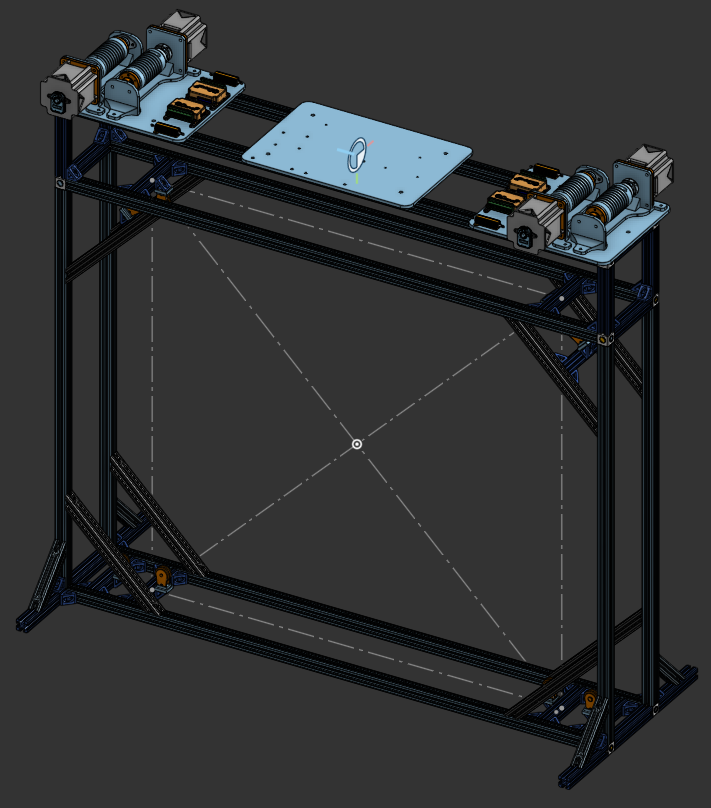
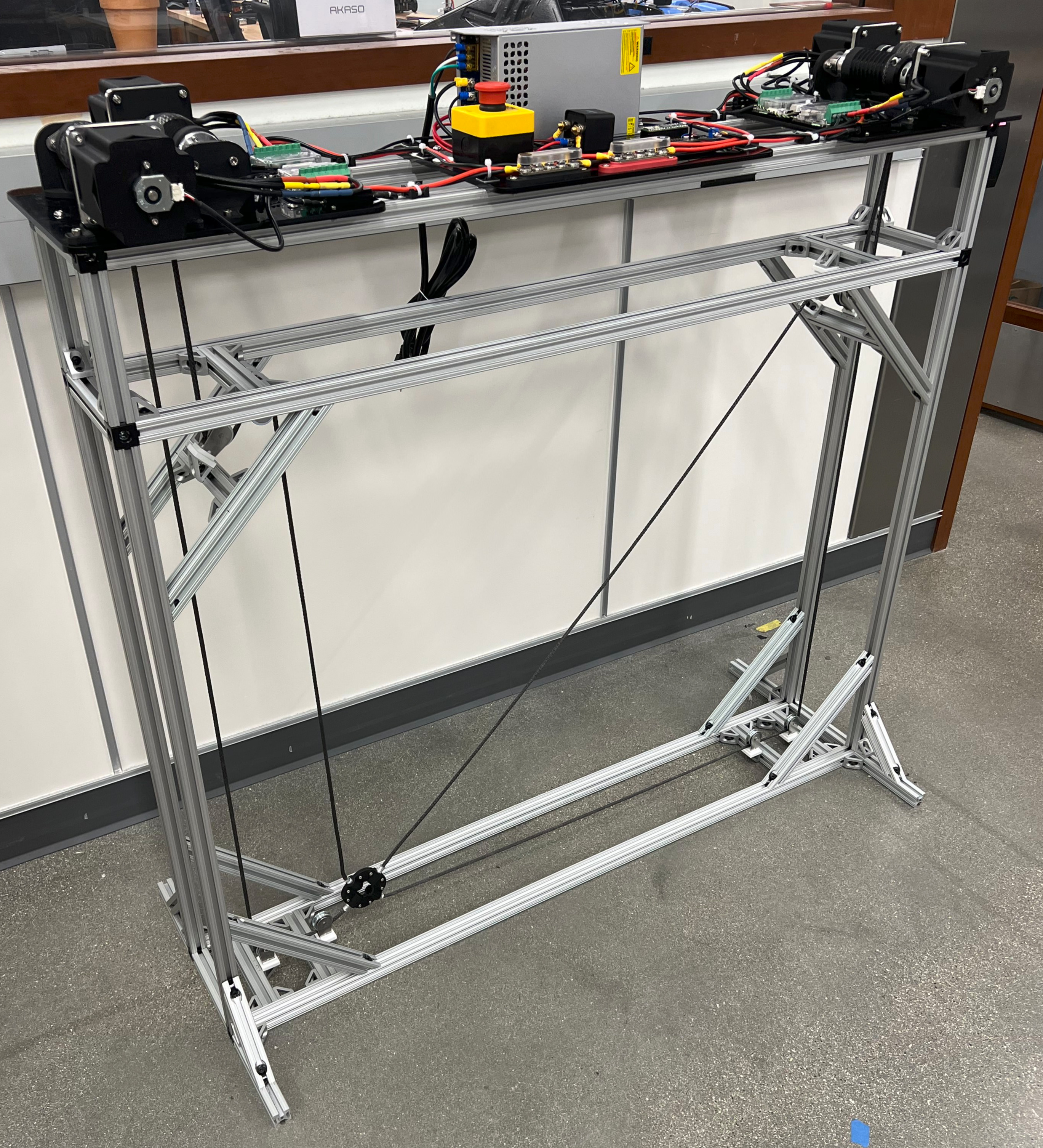
In terms of modeling, the main components of interest of this design are the motor-drum asseblies that are used for winding and unwinding the cables. The drums are threaded, which allows for predictable winding and unwinding of the cables. These drums have heat-set inserts that are used to mount the shaft collars, which then secure the drums to the shafts that are coupled with the motors.
Control System
To move the end-effector while keeping the cables in tension, a custom force-based controller was designed and tuned (block diagram shown below).
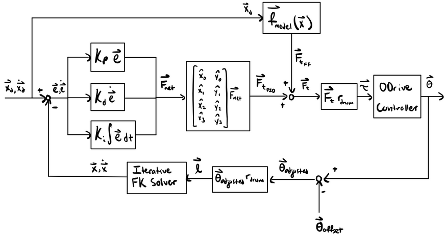
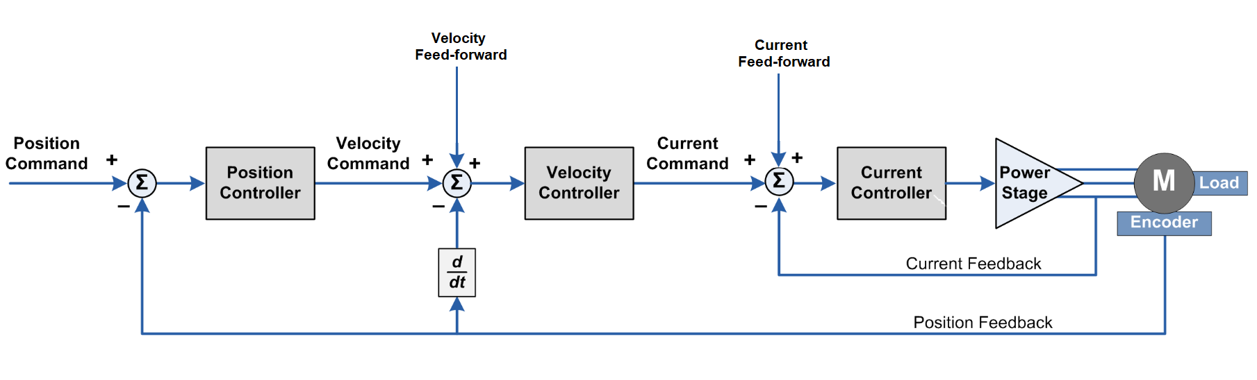
In this control system, position and velocity errors generate a 2D force in the workspace plane, which is then broken down into the 4 specific cable contributions. The tensions from the PID controller are added to estimated tensions from a feedforward model that estimates the tensions based on end-effector position. The sums of the PID and feedforward tensions are converted to torques and sent to the ODrive controller (shown below).
One of the main motivations for designing the force-based controller is that it makes it easier to keep the cables in tension when the motors are in torque control mode. Another route that could have been taken would have been to operate the motors in position control mode while also sending velocity and torque feedforward commands, but this would likely require a tension distribution algorithm to prevent the cables from having slack.
Performance
In order for the controller to function correctly, the position and velocity errors must accurately reflect the current state of the system. Since forward kinematics is used to estimate the current end-effector position, I did some testing to see how accurate this estimate is. For my testing, I moved the end-effector to various points in the workspace and logged the estimated and actual end-effector positions (actual position estimated using apriltags).
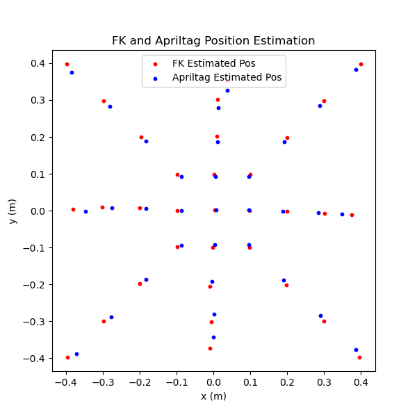
While there is some error as the end-effector moves towards the bounds of the workspace, the forward kinematics estimate is accurate enough for the application. In addition to testing the forward kinematics estimate, I also generated some movement plots to see how well the end-effector is following straight-line trajectories at different speeds.
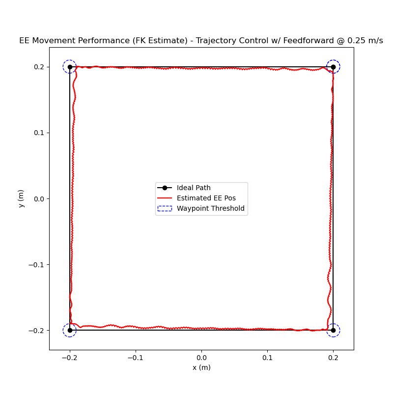
0.25 m/s
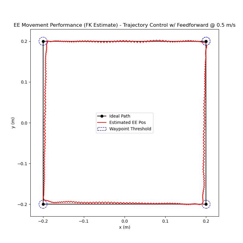
0.5 m/s
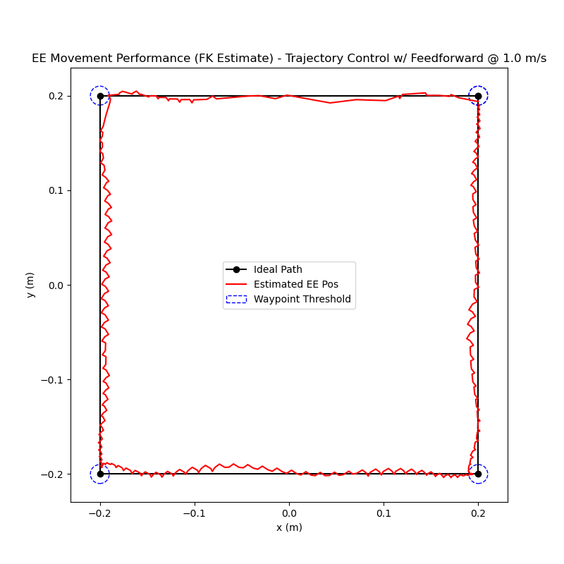
1 m/s
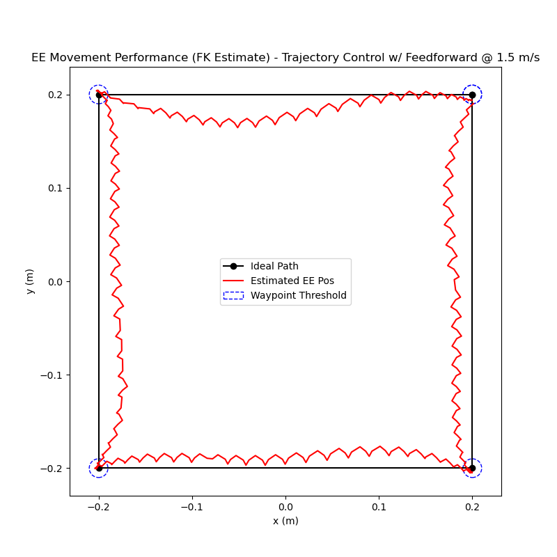
1.5 m/s
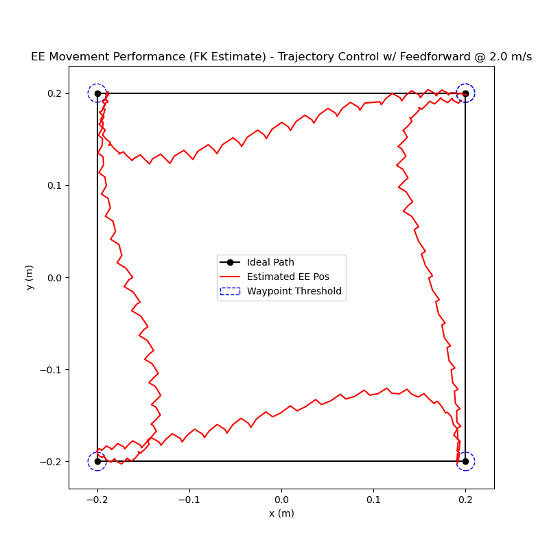
2 m/s
Testing in Water
Movement while submerged
Before testing in water, modifications were made to the design to protect the electronics from being damaged. Watertight enclosures were purchased and machined to accomodate all of the wiring necessary to connect the electronics. Also, the power supply was moved off of the robot frame where AC power from the wall outlet does not have to be as close to the water and the 24V, GND, and CAN cables can be plugged into their respective connectors on the frame.
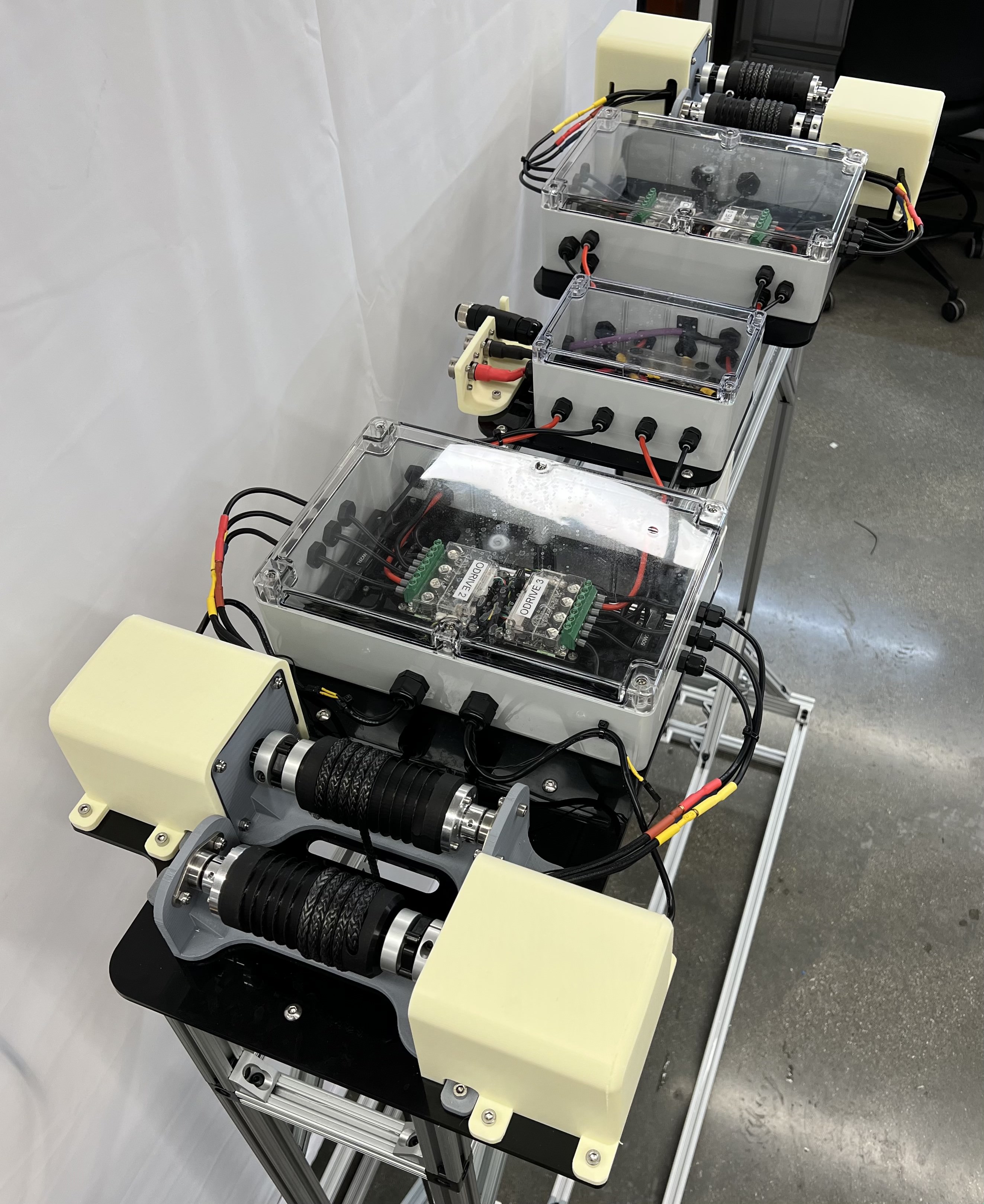
Watertight Enclosures on the Robot Frame
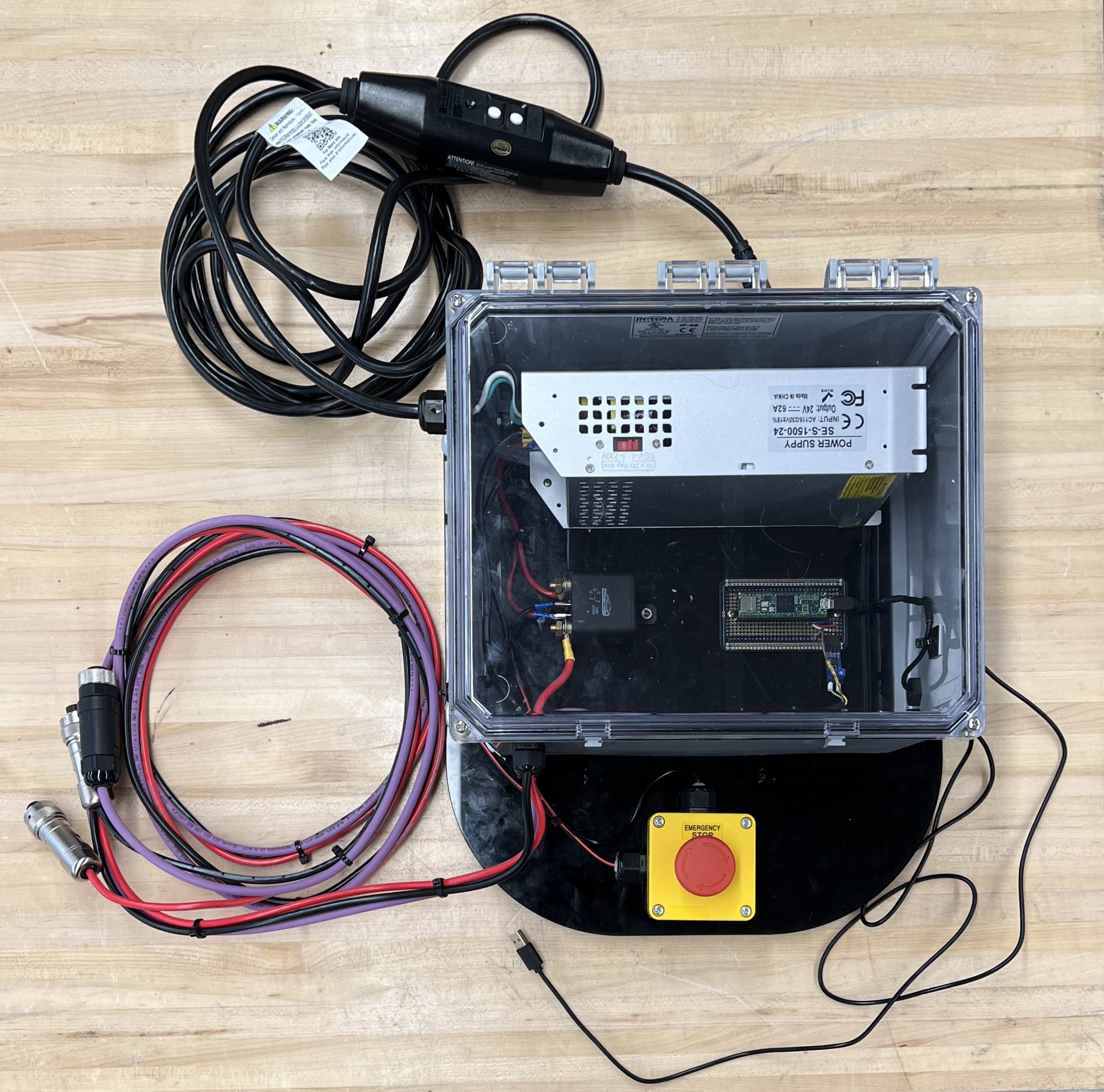
Watertight Enclosure for Power Supply
In addition to these changes, another frame was added to the bottom of the system to increase the height by 8 inches since the Northwestern University Olympic pool (where the testing was being completed) had a minimum water height of 4 feet 2 inches and the workspace frame was a little too short.
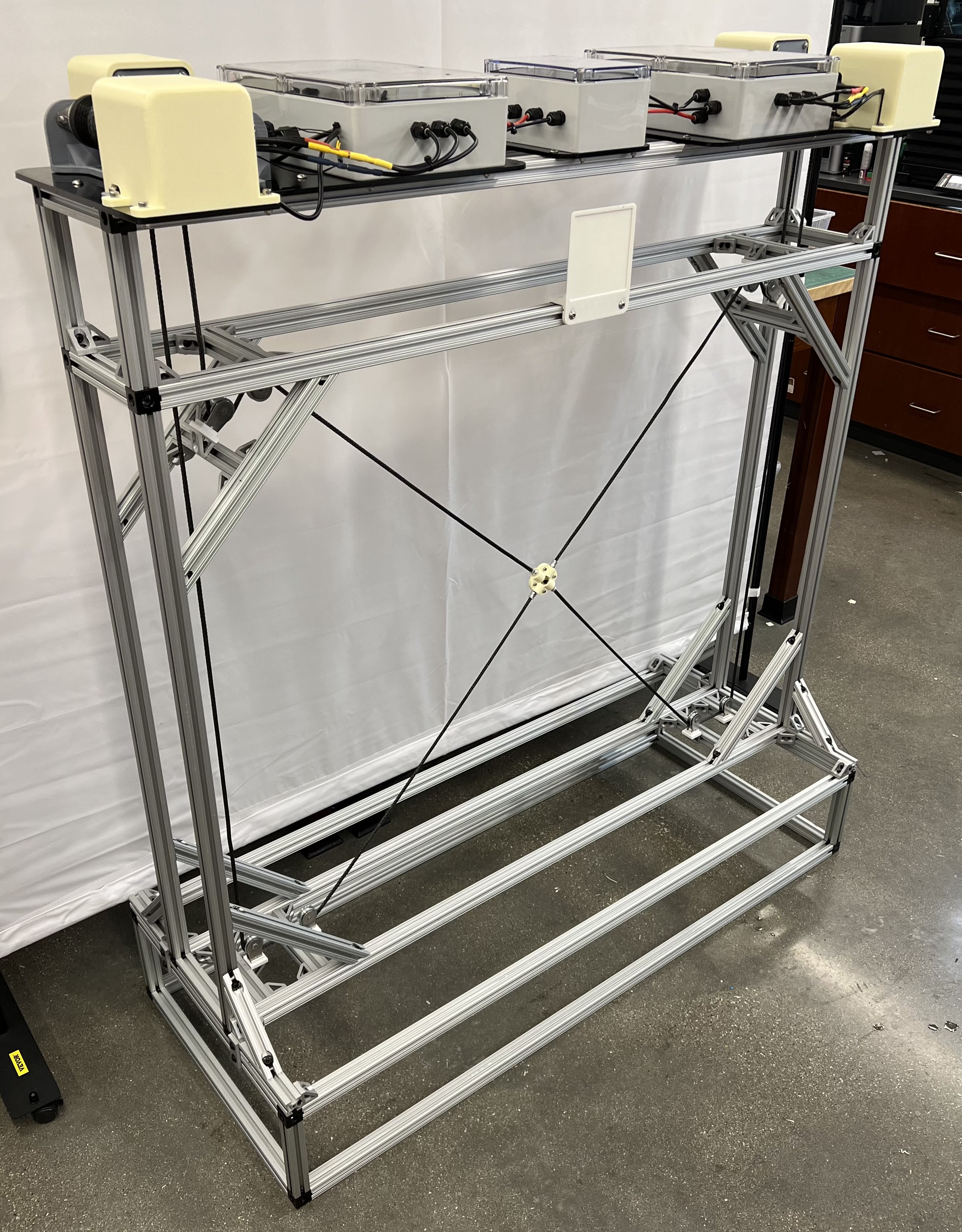
Updated Design with Watertight Enclosure and New Frame
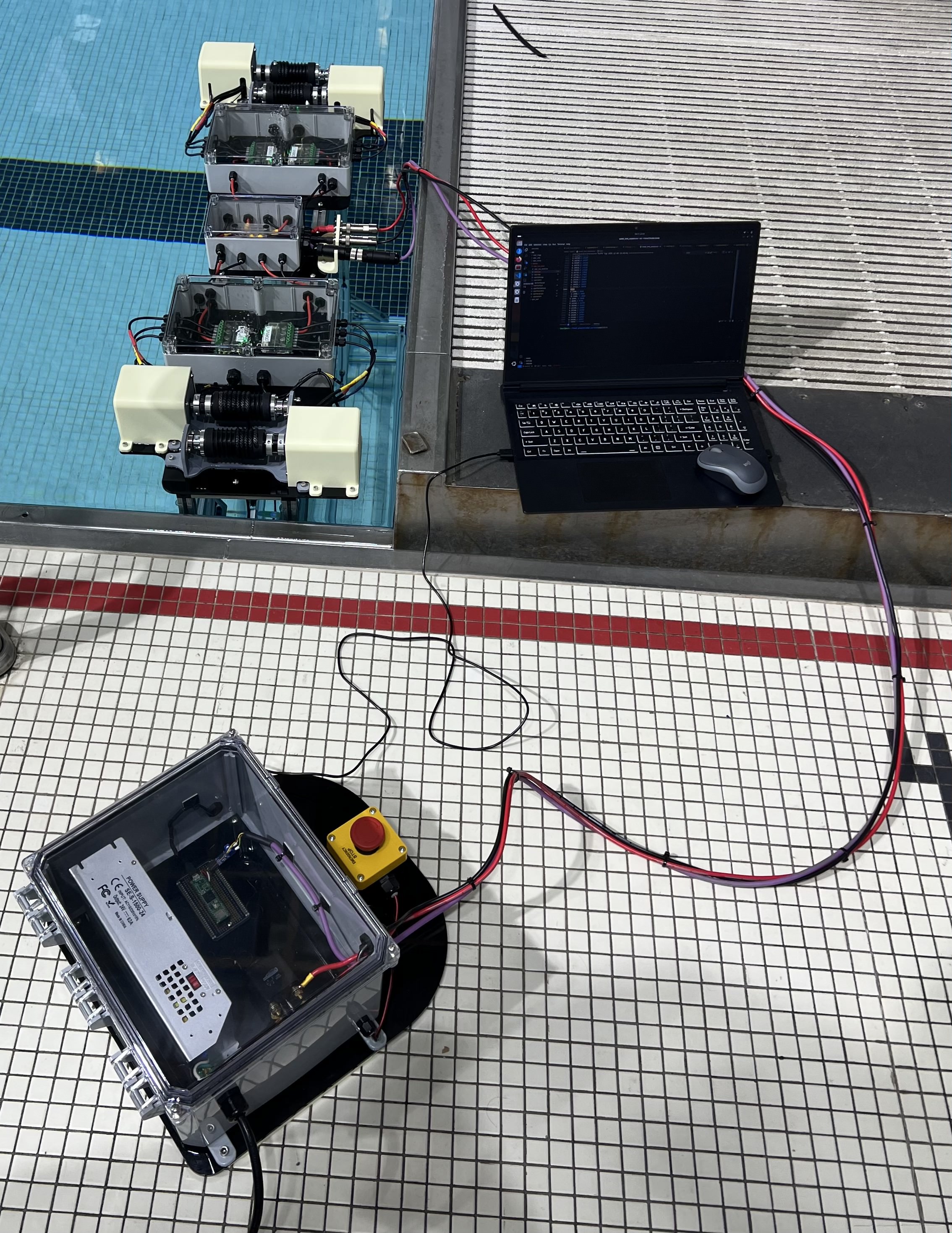
Testing Setup
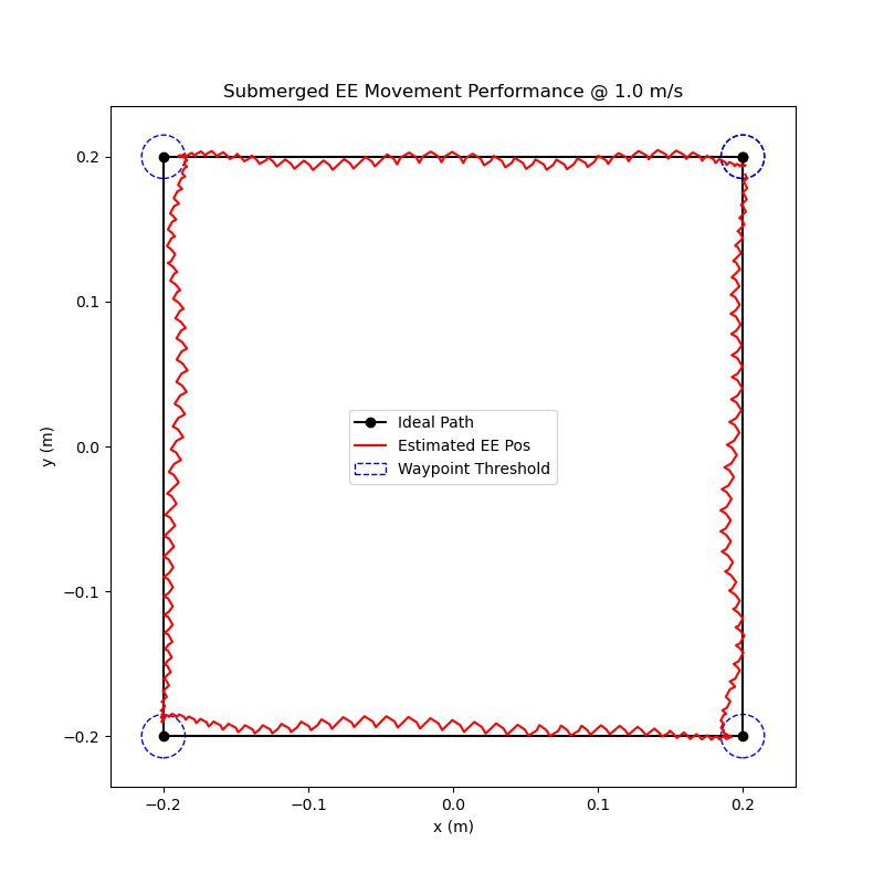
Water Performance
In order to compare how well the robot works while submerged, I completed the same waypoint tests as I did previously (results shown below). Overall, the results did not differ very much at all. This could be due to the small size of the end-effector, the motors being more powerful than necessary, or a combination of both. Either way, the results show that my design can serve it’s intended purpose of operating while submerged in water and has room to increase the end-effector size if necessary.

0.25 m/s
0.5 m/s
1 m/s
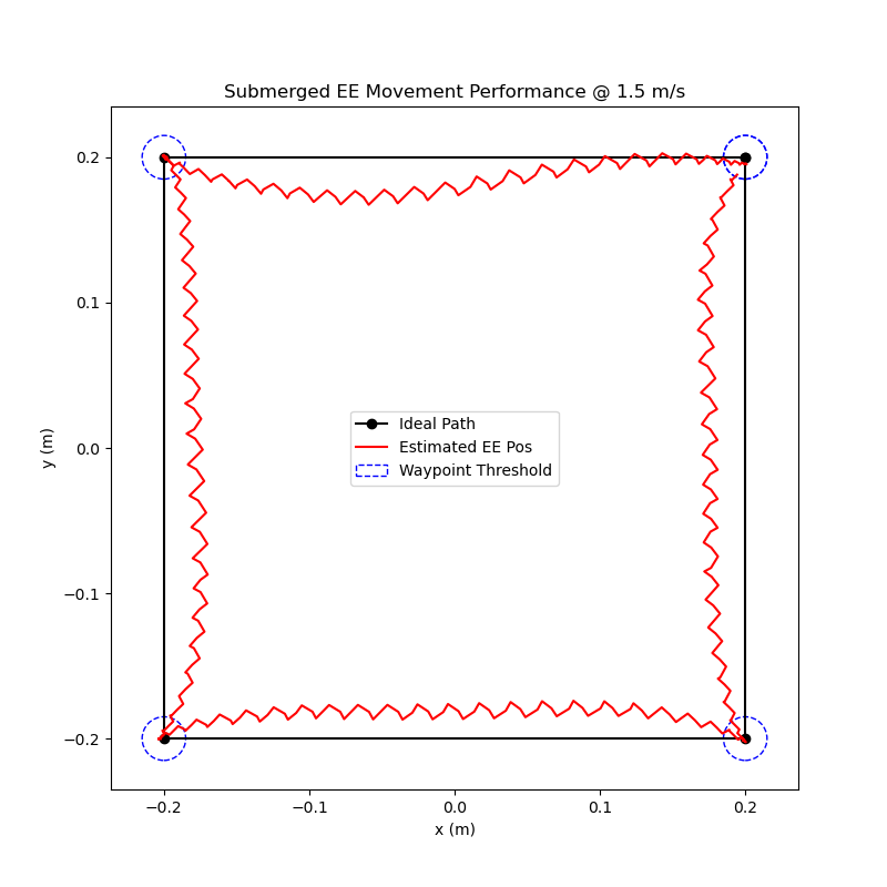
1.5 m/s
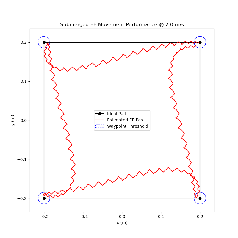
2 m/s