Ping Pong Robot from Scratch
This is a 10 week project with the ideal goal of building a omnidirectional robot from scratch that is capable of returning ping pong balls to a player. The idea behind this project is that this robot would sit on the opposite side of a ping pong table from a player and move accordingly to return the balls. Within this timeframe, my objective was to achieve the most effective level of functionality possible—whether that meant reliably returning the balls or at least tracking their movement and responding accordingly.
Demo
Software
To start on the software side of this project, I began by writing some low-level code to read from and write to the 4-channel driver board I2C registers so I could set motor speeds and read encoder counts. Here are some simple, open-loop movement tests:
From this point, I started writing ROS nodes so I could operate the robot wirelessly. My idea was to have one node running on the Raspberry Pi and the rest running on my laptop so the majority of the computations necessary during operation will be handled on my laptop, and the Pi just needs to interact with the hardware. A block diagram of the system ROS nodes is shown below.
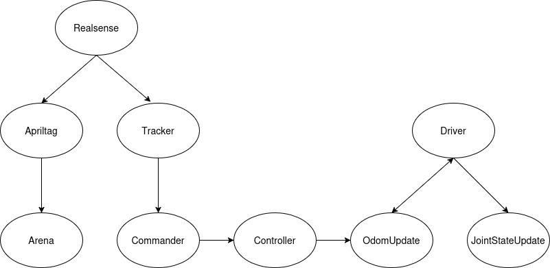
Nodes
- Driver: This is the node running on the Pi. With the first robot design, this node only needed to read encoder counts and send motor speeds to the 4-channel driver. After the redesign, this node needed to read encoder counts, IMU data, and generate PWM signals using I2C communication in addition to sending digital outputs to the motor drivers to set motor directions. This node subscribes to the
/wheel_speedstopic to command the motors and publishes to the/wheel_anglesand/imu/data_rawtopics so the robot odometry can be updated. - JointStateUpdate: This node subscribes to the
/wheel_anglesand/wheel_speedstopics and publishes to the/joint_statesso the robot’s joints update accordingly in rviz. - OdomUpdate: This node subscribes to the
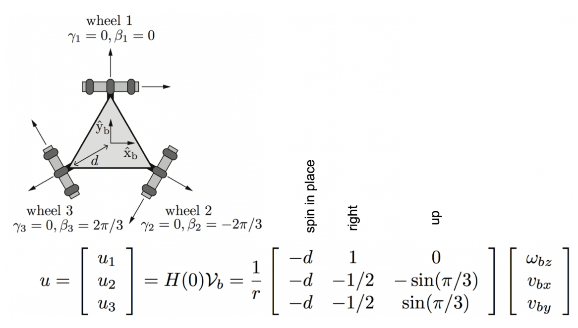
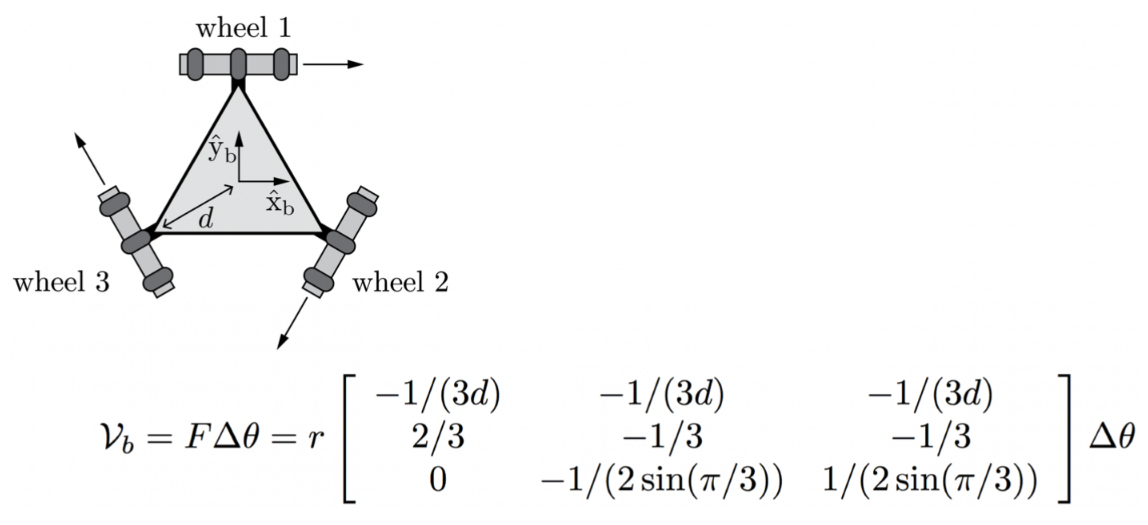
/wheel_anglesand/cmd_veltopics. It uses the wheel angles to update the transform between the odom frame and the base_footprint, and converts the twist message to wheel speeds, which is then published to the/wheel_speedstopic. The kinematics and odometry calculations completed by this node are based on the equations below from “Modern Robotics: Mechanics, Planning, and Control” by Kevin M. Lynch and Frank C. Park.
- Controller: This node subscribes to the
/goal_posetopic. It compares this goal pose with the current robot position and generates a twist message using a proportional controller (integral and derivative may be added later) that is published to the/cmd_veltopic. - RealSense: This node is from the following repo:
realsense-ros
Using an Intel RealSense D435 Camera, this node publishes to multiple camera topics including color and depth images. - Tracker: This node subscribes to the camera topics. It uses OpenCV to identify the 3D position of a ping pong ball, and publishes it as a pointstamped message to the
/ball_postopic. - AprilTag: This node is from the following repo:
apriltag_ros
This node subscribes to the color image topic and broadcasts transforms for the two apriltags used in the system. - Arena: This node listens to the apriltag transforms broadcasted on the tf tree, and sets up an arena in rviz to represent half of a ping pong table by publishing a marker array to the
/visualization_marker_arraytopic. This node also broadcasts the necessary transforms so the robot position relative to the table is updated correctly. - Commander: This node subscribes to the
/ball_postopic. It takes the position and determines a suitable goal_pose for the robot and publishes it as a posestamped message to the/goal_posetopic.
Mechanical Design
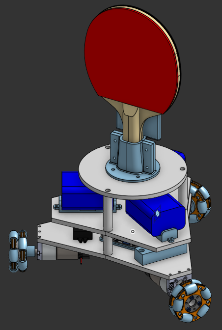
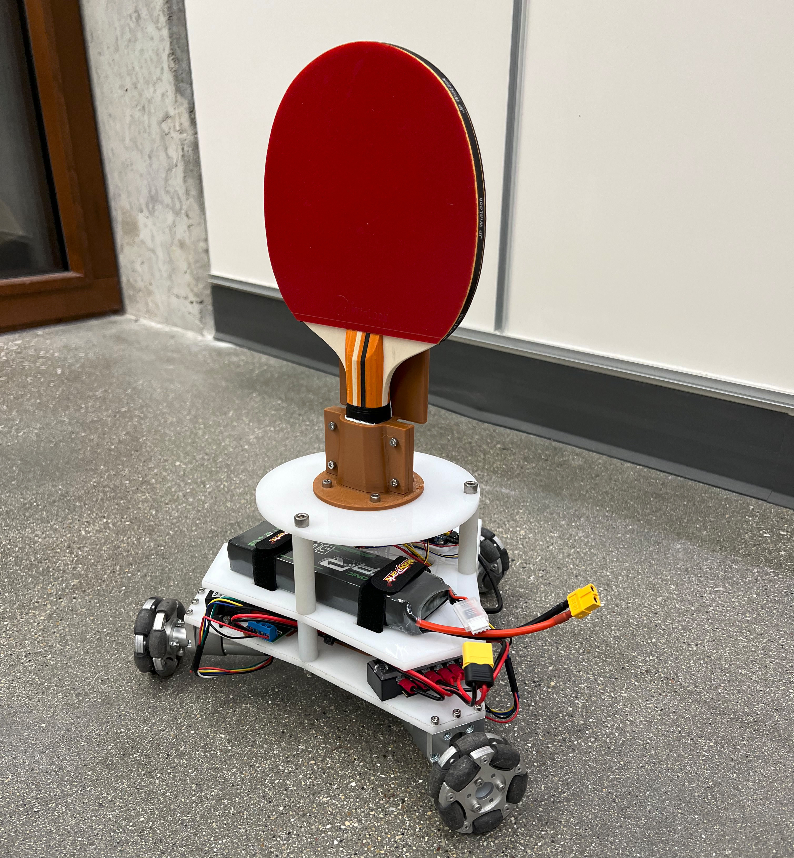
To start this project, I began by picking out parts and making a CAD model in Onshape. I decided on using a Raspberry Pi 5 running Ubuntu 24.04 LTS to operate the robot, which would allow me to use the most recent ROS2 distribution (Jazzy) that’s also installed on my computer. For actually moving the robot, I decided on using three 12 V brushed DC encoder motors from Pololu with 60 mm omniwheels connected to a 4-channel encoder motor driver from Hiwonder that uses I2C communication. Most of the parts are purchased, but a few of them are custom made (the 3 different levels are cut out of acrylic and the Raspberry Pi spacer, motor driver spacer, battery mounts, and paddle mount are all 3D printed with PLA). The model and physical robot are shown below.
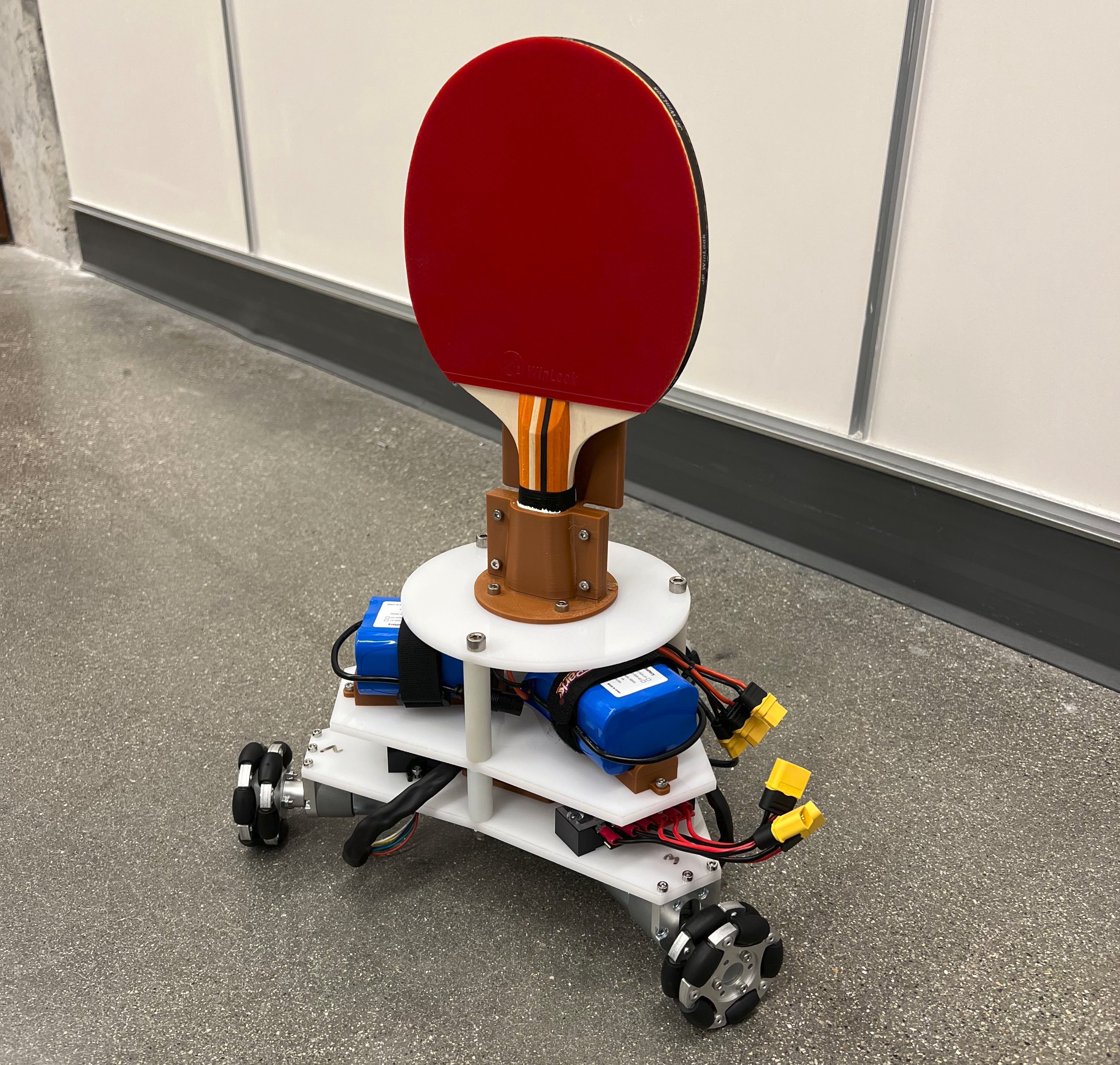
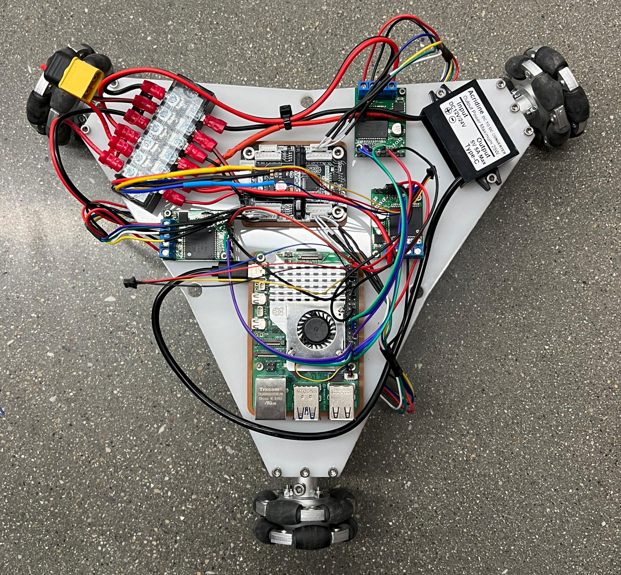
After building this first version of the robot, I ran into a few issues: struggles accelerating from rest and inaccurate odometry updates. In order to address these issues, the robot was redesigned to include new motor drivers with higher output current, a PWM driver to interface with the drivers, an IMU, and a new battery (which resulted in a loss of about 1 lb). The redesigned robot is shown below. I still use the 4 channel encoder motor driver to read the encoders, but I use the PWM driver board to generate the PWM signals necessary to move the motors. The new motor drivers use one PWM signal and two digital signals per motor to set motor speed and direction. These new additions resulted in better performance.
Additional Components
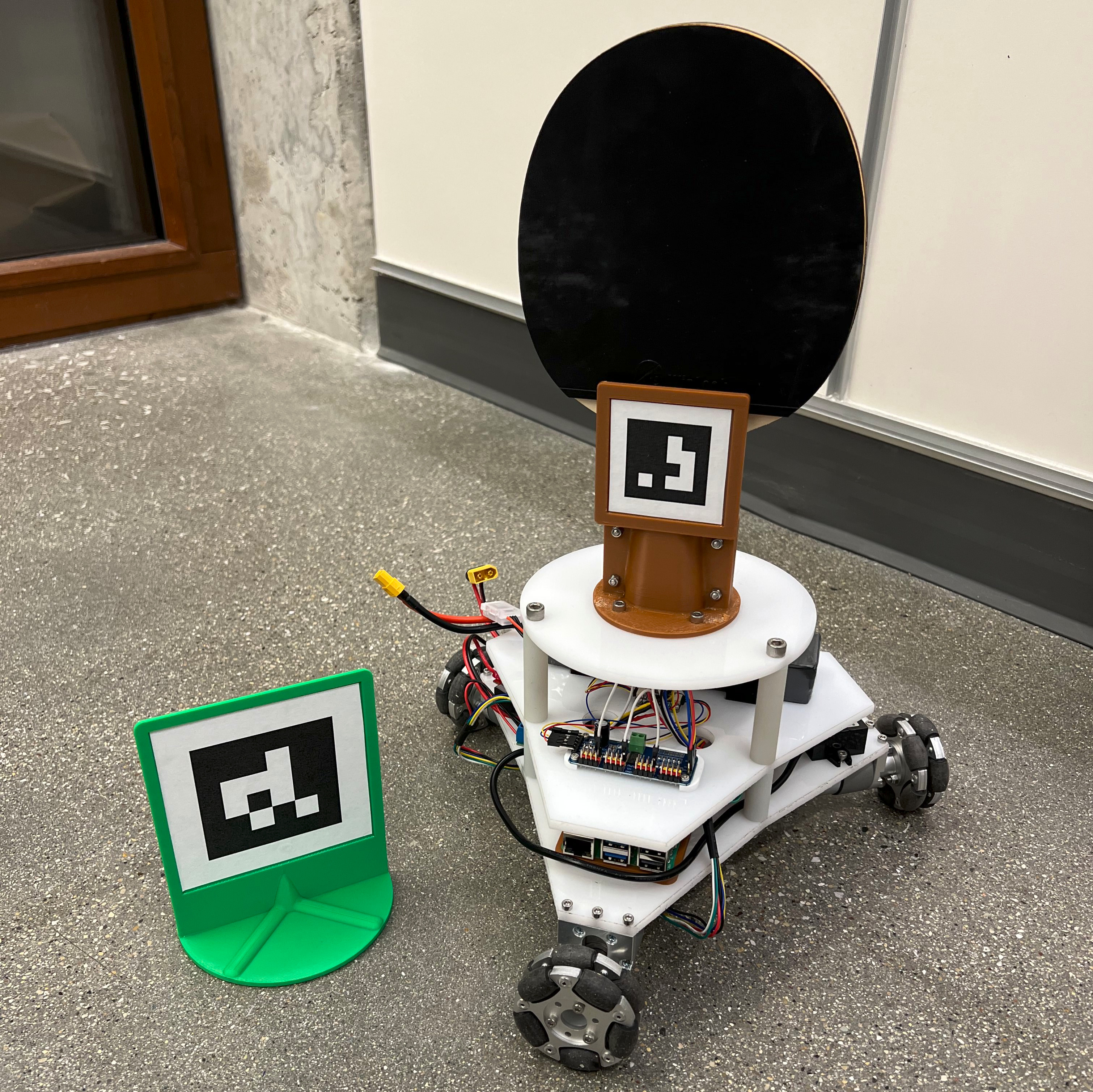
In addition to fabricating the robot, I also made an apriltag setup consisting of two tags that will be used to set up the location of the robot relative the table when the ROS nodes are started.
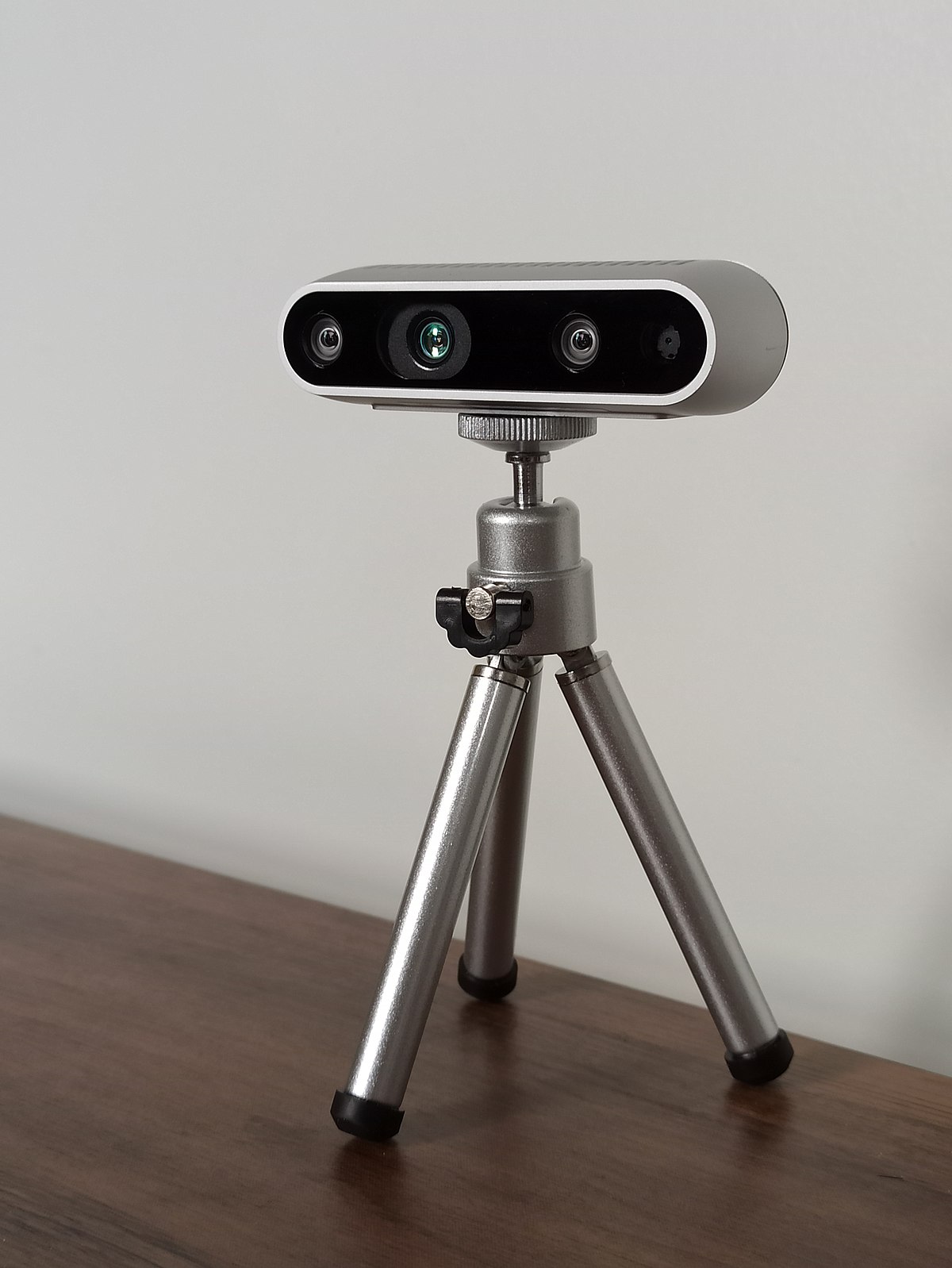
Also, for the computer vision aspect of the project (tracking the ball and setting the arena using apriltags) I am using an Intel RealSense D435 camera, which has depth capabilities.