Low-Level Motor Controller
The goal of this project was to build and program a motor controller development board using a PIC32MX170F256B microcontroller that can be used for brushed dc motor position control.
Overview
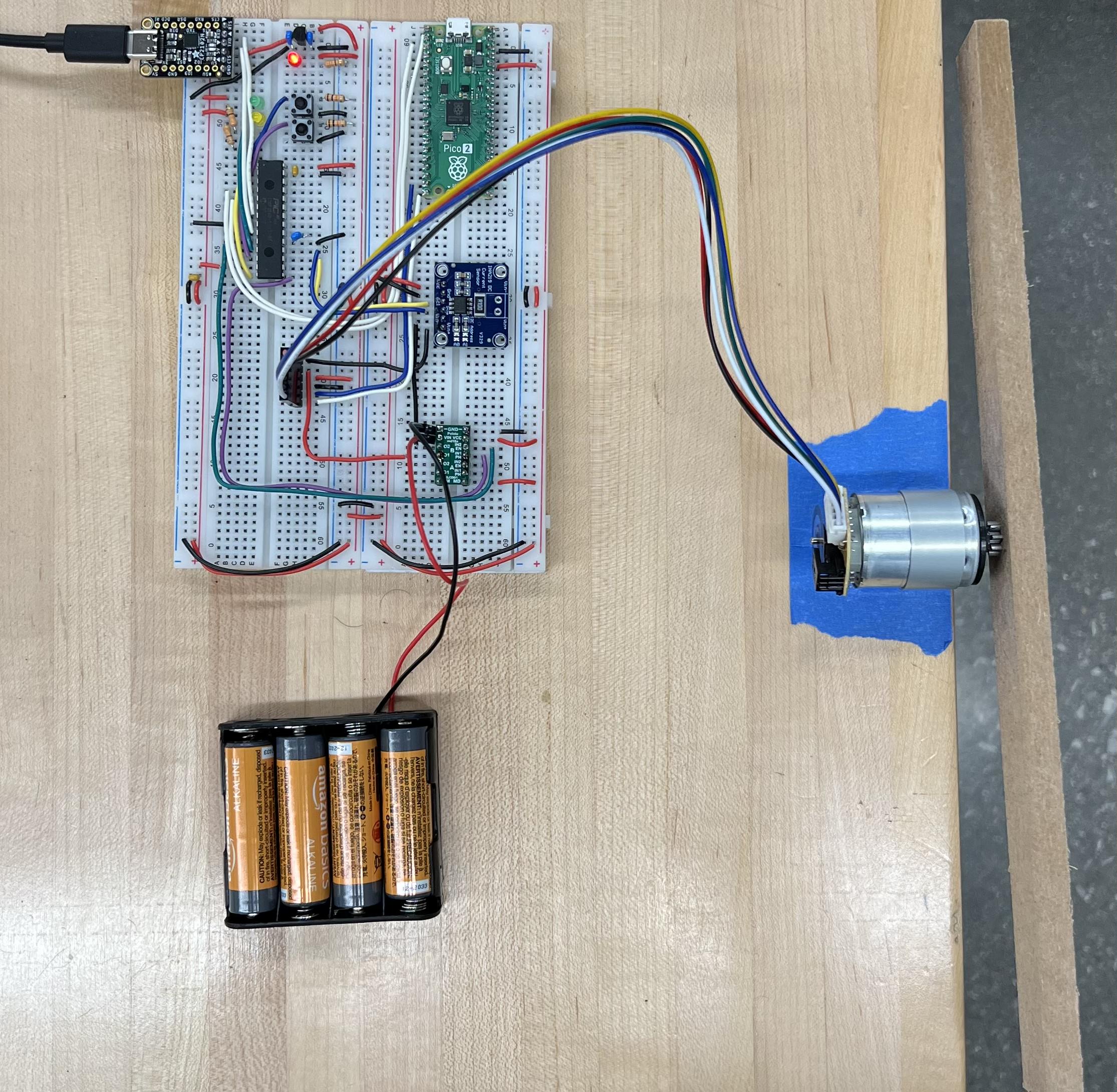
This was completed as the final project of Northwestern University’s ME 333: Intro to Mechatronics, so the hardware used in the system was selected for all of the students in the class. In addition to the PIC32, the system consisted of a Raspberry Pi Pico 2 used for reading encoder counts, a CP2102N USB to serial converter, an INA219 current sensor, a DRV8835 motor driver, a DC motor with load beam, and a battery pack.
Development Board Setup
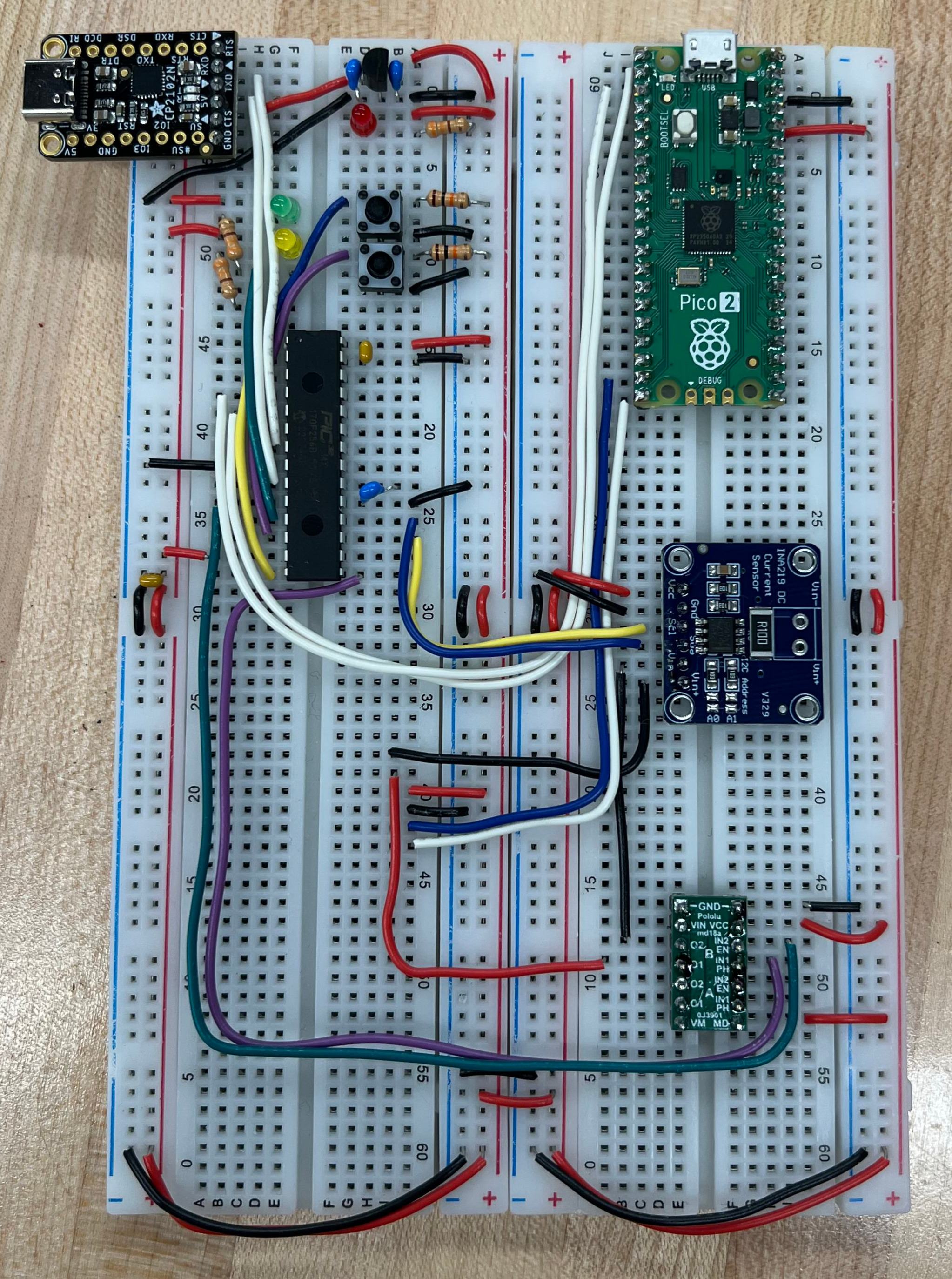
The top-left of this board includes the PIC32, USB to serial converter, and other electrical components necessary for programming the microcontroller. When the USB to serial converter is connected to a computer, 5V is supplied to the system, which is then reduced to 3.3V by a voltage regulator. This 3.3V voltage is used as a power supply for all of the components on the board. The USB to serial converter communicates with the PIC32 using one of the PIC32’s UART channels. The Pico communicates with the PIC32 using another one of the PIC32’s UART channels, the current sensor communicates with the PIC32 using I2C, and the motor driver is commanded using a PWM signal and a digital output from the PIC32.
Testing Setup
Programming
The programming for this project consists of two main components - code running on the PIC32 written in C and code used for interfacing with motor controller written in Python.
For the C code necessary for this project, header files for interacting with the peripherals were provided, but the main code for operating the system was developed from scratch. Two interrupts and their corresponding interrupt service routines were set up for controlling the motor - one for current control that executes at a frequency of 5 kHz and one for position control that executes at frequency of 200 Hz. The necessary PWM signal for driving the motor is generated using one of the PIC32’s output compare peripherals and has a frequency of 20 kHz. In addition to these ISRs, the main while loop that is continually executed has a switch statement that checks for commands from the Python code and executes the corresponding commands (shown below).
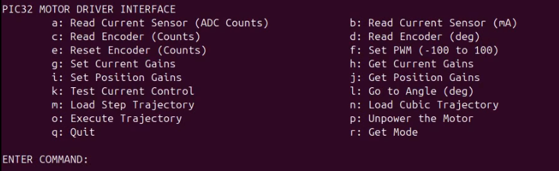
The Python code used in this project uses the pyserial library to communicate with the PIC32. It creates a terminal interface that is used to operate the motor controller by sending and receiving commands through UART communication with the PIC32. The terminal interface with the list of commands is shown below.
In order to operate the system, the C code must be loaded onto the PIC32. In order to do this, the first step consists of compiling the C code using the make command and the corresponding makefile for this project. Then, the reset and user buttons are pressed in quick succession to put the PIC32 in bootloader mode, and the code is uploaded using the make write command with the board connected to the computer. From here, the PIC32 is programmed and the Python file can be run the control the motor.
Control System
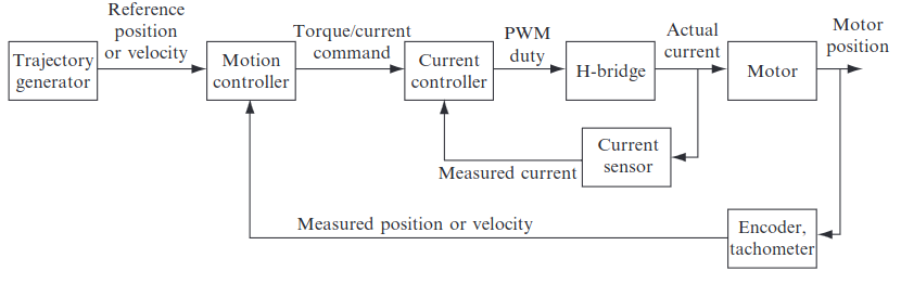
In order to find the necessary gains to perform trajectory tracking, I started with testing current control by seeing tracking a 100 Hz square wave that alternates between 200 and -200 mA. Once I had a good response for current control, I switched my focus to the position control. I tested with step and cubic trajectories and found gains that resulted in good responses. The plots of the responses and trajectories are shown below with their associated gains.
Current Control Response
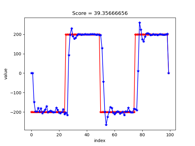
Gains Used: Kp = .08, Ki = .07975
Trajectory Tracking Results

Gains Used: Kp = 10, Ki = .03, Kd = 250

Gains Used: Kp = 10, Ki = .03, Kd = 1200