Road Bike Modeling and FEA
The goal of this project was to design a CAD model of a system with complex geometry using solid and surface modeling techniques. Components of this model were then used to perform a structural FEA simulation.
Group Members
Drew Bailey, Ty McCaffrey, Logan Boswell
Overview
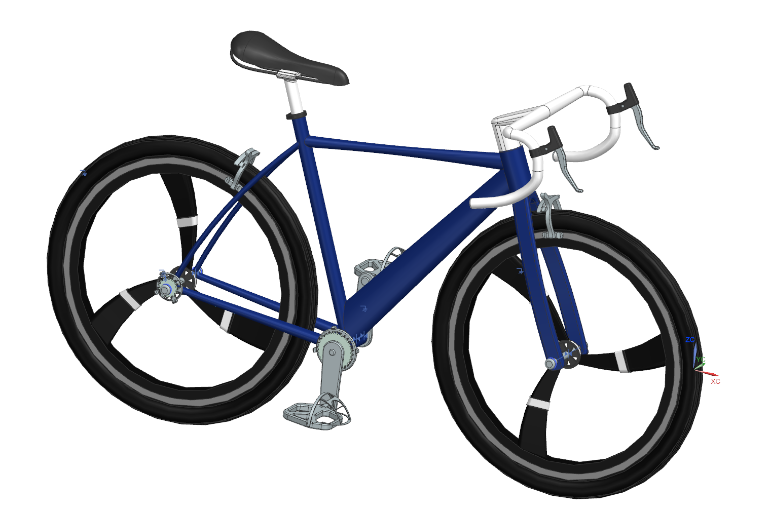
For a final project in the Georgia Institute of Technology’s ME 4042: Interactive CAD and FEA, my group decided on designing a road bike and performing a structural analysis to see how it deforms under a rider’s weight. The completed assembly is shown below.
My Focus
In this project I was in charge of modeling everything besides the wheel and pedal assemblies and perfoming the FEA simulations on the bike frame and fork.
Modeling
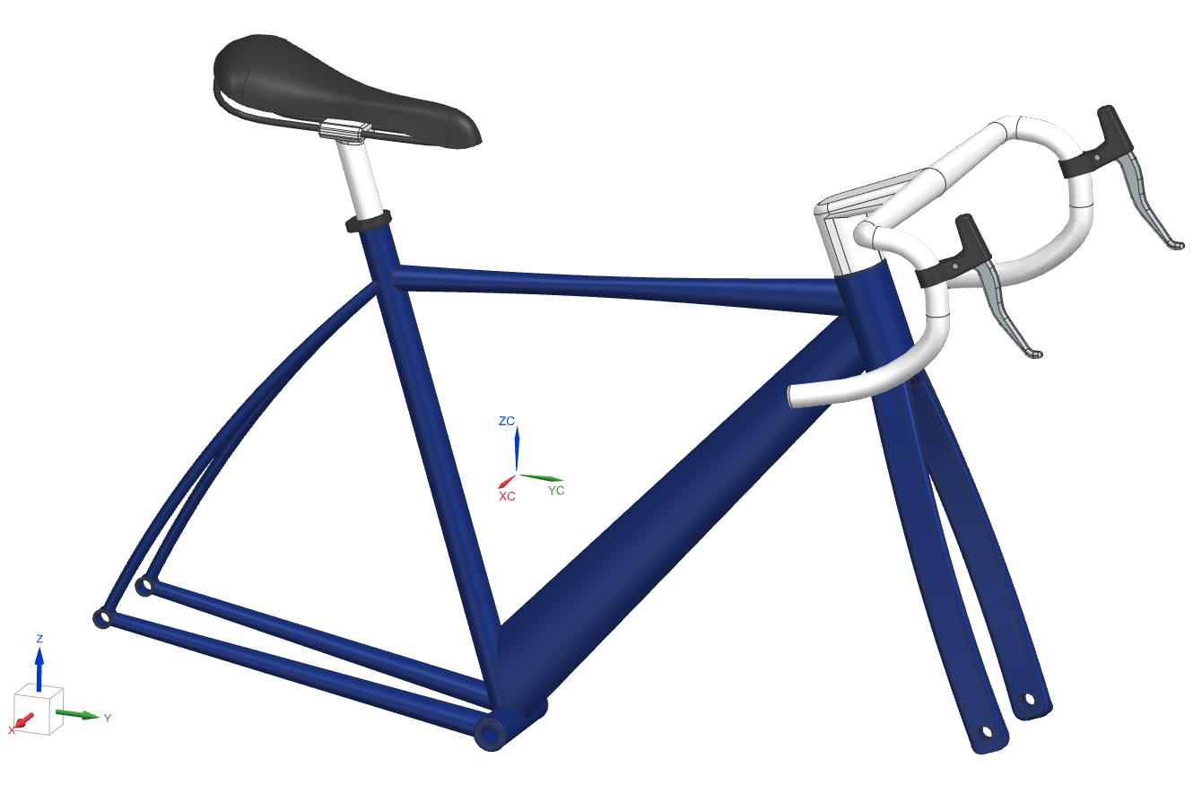
I used solid and surface modeling techniques to create my assigned parts. The most difficult part for me to make was the bike frame due to its complex geometry, which consisted of many surfaces. The assembly of my assigned parts is shown below.
FEA
Structural FEA simulations were performed on the frame and fork models. My group and I chose Aluminum 6061 for both models and assumed that the person riding the bike weighs 150 lbs. A simulation was completed on each of the models individually with a fixed constraint on the frame-fork connection and 1/4 of the rider weight applied to each of the places where wheels are connected. The simulation results are shown below for both models.
.gif)
.gif)
The results from these simulations included max stress of 84.06 MPa and max displacement 2.25 mm for the frame and max stress of 68.45 MPa and max displacement of .435 mm for the fork. Hand calulculations were completed to verify the max displacements of the fork and frame and the hand-calulated max displacements were 1.942 mm for the frame and .391 mm for the fork, showing the simulation yielded reasonable results. As for the max stresses, the yield strength of Aluminum 6061 is 241 MPa, so the models are not at risk of breaking.